 New features added to version 4


|
Projects management
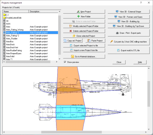
In the previous versions all the Projects were saved in a single fixed folder. Many users asked to add the possibility to select different folders, to better organize
their work. To help them I added the possibility to create, modify and delete new subfolders directly inside the Project management dialog, and also added a copy&paste feature
for Projects. Then you can select the current Folder just double clicking on it, and new, imported or pasted Projects will be added there.
|

|
2D Graphic input value procedure
This is a totally new feature.
Let's start from the beginning.
In the upper part of every page of the Project wizard you can see many edit controls, where you can insert parameters and values to define your project. For example, when you are applying a spar, you can define at least the spar's placement. You will do that inserting the right values in the included edit boxes.
With this new technology you can also send values from the 2D Graphic view to the edit boxes in a very simple way.
The edit boxes enabled to get values from the 2D Graphic view have a coloured background, and when they are active in the actual 2D Graphic view page the text is rendered in Red.
Depending on the type of value (coordinate, length/size/distance, angle), the colour of the background is different.
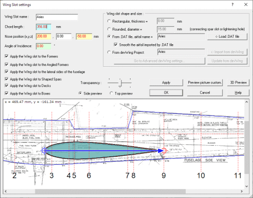
When you set the focus to an edit control enabled to get a value from the 2D Graphic view (we will just call it graphic enabled), you will see in the 2D Graphic view some control points. Just click them and move them to the right position to apply the new value.
After you move the control point to the new position and click there the Left mouse button, the new value will be copied to the edit box and the Update/Modify button automatically pressed, so you can see immediately the final effect of the new value.
See below the example of what you see when you set the Chord length in the edit control of a Wing Slot:
|

|
Weight calculation of the fuselage
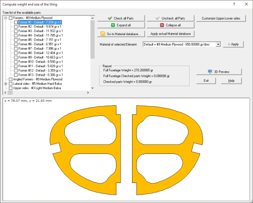
Using this new feature you can compute the Weight of the fuselage.
You can apply default or customized materials to every part or group of Parts, then you
will see the weight of the total wing of or some selected parts.
See below the picture of the Weight dialog:
|

|
Cam features
New Cam features:
- 3D Preview and export to STL file of every part. In this way you can the use your 3D printer to create the parts!
- Multiple sheets on a single cutting job. As for example balsa sheets are usually short, you can select to place multiple aligned sheets on the cutting table, and the application (during the nesting phase) will place the parts taking care to cross the joining lines between sheets.
- More customizations features for parts going to be cut. You can change the label, the number of pieces, rotate them and so on...
- Before cutting the parts you can adjust the sense of rotation of the cut for all contours and islands in one shot, to have a better cut according to the rotation sense of your milling tool.
- Improved management of bridges for little islands/holes
- Label engraving performed now before cutting the parts.
|

|
Improved former interpolation and real circle formers.
A lot work has be done to improve the way interpoled formers are generated.
Now also for complex shapes when the surrounding control formers have the same number of control points, the result is very accurate.
And when moving an interpoled former along the fuselage, you can see in real time the final shape of the former.
You can also force some control former to be a real circle, this is very useful for example when the first former must match a spinner.
In the standard way the height and width of the ellipse are calculated by the side/top views, but sometime these are not accurate enough.
You can also force to diameter to a fixed value.
|

|
Improved boxes.
Now you can specify a downward and rightward angle for the front face of boxes.
This is very useful when you use it to mount the engine, and in this way you can apply those angles directly to the front face, instead of using spacers.
|

|
Improved lateral sides.
Now you can apply a second internal lateral side, with different length, thickness, formers slots, lightening holes and splits.
This can be used for example to enforce the front part of the lateral side, using thin plywood internally attached at external balsa.
Also the 3D preview of sheetings has been greatly improved. Now you can optionally show in the 3D wing slots, formers slots and lightening holes.
This feature is optional as it can slow down the computing phase of the rendering.
|

|
Wing slot improvements.
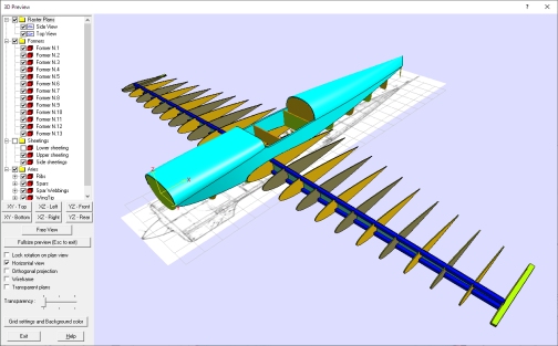
Now you can import a devWing Project as a Wing slot.
In this way you have a lot of advantages:
- devFus will consider the real 3D shape of the wing, including tapering, dihedral, airfoil interpolation.
- devFus will also optionally apply all elements like Leading edges, Trailing edges and Spars to the fuselage structure, and each of them can slot every element of the
fuselage, according to user's preference.
- The 3D preview will show also the full wing, so you can have a preview of the full airplane.
|

|
New feature: Wing fairings.
A wing fairing is the connection between the fuselage and a wing external to the fuselage itself. The wing fairing is often referred also as a wing Karman.
It can affect Lateral sides, Formers, Angled Formers, Shaped Spars, Decks and Boxes.
The wing element must be placed outside of the fuselage. For wings intersecting the fuselage use a Wing Slot element.
The fairing is built by 3 optional ribs and a sheeting. Special protrusions will also be applied to the formers, to reflect the fairing shape.
- Sheeting: The sheeting covers the upper and lower parts of the below ribs. You can just specify its thickness. When exporting parts also the upper and lower sheetings will be created.
- External rib: this rib is placed where the wing will touch the fuselage. Possible options are the thickness and the way the wing elements will slot it, for a devWing Project, specified by the Advanced settings for a devWing imported Project dialog.
- Internal rib: this rib is placed usually just inside the fuselage. Possible options are the thickness, the type and size of the slots where formers are crossed, the placement as a distance from the meanline of the fuselage and the way the wing elements will slot it, for a devWing Project, specified by the Advanced settings for a devWing imported Project dialog.
- Central rib: this rib is placed in the middle of the fuselage. It can be single or doubled. Possible options are the thickness, the type and size of the slots where formers are crossed and the way the wing elements will slot it, for a devWing Project, specified by the Advanced settings for a devWing imported Project dialog.
You can import a devWing Project as a Wing fairing.
In this way you have a lot of advantages:
- devFus will consider the real 3D shape of the wing, including tapering, dihedral, airfoil interpolation.
- devFus will also optionally apply all elements like Leading edges, Trailing edges and Spars to the fuselage structure, and each of them can slot every element of the
fuselage, according to user's preference.
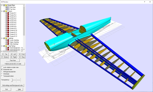
- The 3D preview will show also the full wing, so you can have a preview of the full airplane.
Here a picture of the fairing and the wing:
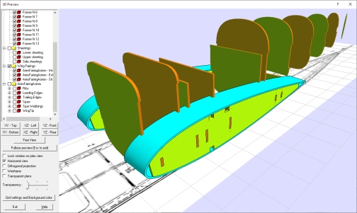
Here just the fairing:
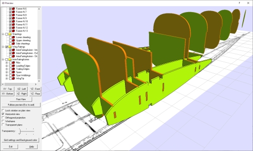
And here the fairing without its sheetings, to show the internal structure:
|

|
New feature: Rudder slots.
A Rudder slot is the same as a Wing Slot, but applying the wing element vertically, like a rudder.
You can refer to the Wing Slot description, as it's the same as for Rudder slot.
|

|
New feature: Rudder fairings.
A Rudder fairing is the same as a Wing fairing, but applying the wing element vertically, like a rudder.
You can refer to the Wing fairing description, as it's the same as for Rudder fairing.
|

|
New feature: Canopy slots.
A Canopy Slot is the Slot applied to the fuselage for a Canopy.
It can affect Upper sides, Formers, Angled Formers, Shaped Spars, Decks and Boxes.
To define a canopy You can setup the position of the two points rendered in blue in the above picture and the front and rear angle.
You also apply three parts to cover the canopy slots. For each part you can define the thickness, an optional enlargement, and Holes. You can see the result in 2D or 3D preview.
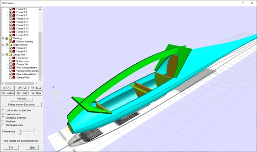
Cause the double curved nature of the upper sheeting, the simplest way to apply the canopy slot it to cut it after you installed the sheeting. To help you to make an accurate cut you can use the Cutting jig elements.
In this way you can build a simple external structure that will drive you cutter blade. See the 3D preview to check the way this structure is build.
You can also export the canopy as a STL file, selecting of you want a bulk canopy, or just as thin as the upper sheeting.
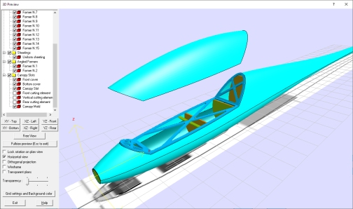
Here a picture of the Canopy slot:
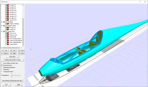
You can see here also the Mold of the canopy, you can then export it as a STL file:
And here cutting jig structure:
|

|
Many others little improvements
Here a brief list of other improvements:
- By the main menu you can specify to keep the default dialogs size not only at full screen, but also reduced to the
dimension of the main window. This because some users want to use devWing on large screen with another application side by side.
- Faster saving/loading of a project
- Mouse pan in the zoomed 2D preview, just using click and drag. Before the only option was use the scroll bar.
- Also angled formers parts now can be kept united if split, before this was possible only for standard formers.
- Now you can copy & paste lightening holes between every part.
- The size of background images is now automatically limited if too big. This in the past caused slow computation.
- A new shape type has been added to the vertical elements of the building jig, to match the external shape of the fuselage.
- You can now make a mirrored copy of Decks and Vertical decks.
- A very big number of internal improvements and little bug fixes has been applied.
|
|
|
 New features added to version 3


|
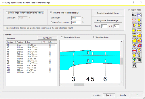
Slots at lateral sides/former crossings Panel
You can apply some slots in the lateral
sides (if any...) where they touch the formers, and some external
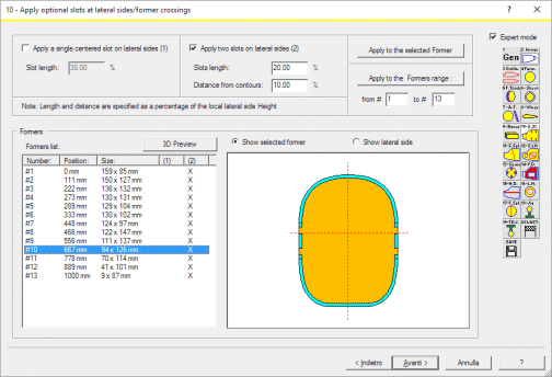
tabs/extrusions to the formers, to create an accurate slotted joint. This will
help to build the fuselage, placing the formers at the right position and
making the structure sturdier See the preview picture in the below image, to
see the lateral side slots:
and the below picture, to see the former tabs:
|

|
Expert mode
Enabling the Expert mode check box, placed in every page of
the Project Wizard, you can fast navigate among Wizard pages, with minimal
recomputing applied. Just press the button of the toolbar to go to the desired
page. You can also save the actual settings using the 'Save' toolbar button. In
this way the user experience is improved, as you don't need any more to scroll
the pages using the usual previous and next buttons of the wizard.
|

|
Full size and resizable pages for the Project wizard
Now the pages of the Project wizard are automatically
rendered as full size, according to your screen dimension. You can also resize
then just dragging the page borders. In this way you can have a better 2D
preview without being forced to use Zoom in.
|

|
New improved 3D Preview
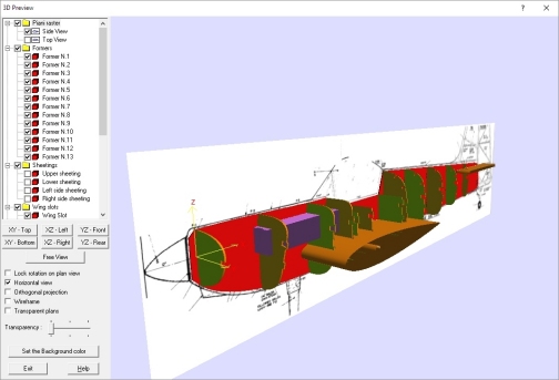
Now the 3D preview is a local window and
no more an external application. This speed up a lot all the process.
You have also:
- a full control over every element, you can switch On/Off them as single
elements or as group of them
- you can also see the background images of the side/top views of the fuselage,
and of the single formers
- you can apply Orthogonal projection and make measurements on the 3D view
- you can select the viewing plan, and lock it if you like
|

|
Cam version: new improved Cutting wizard
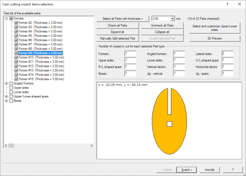
The Cutting wizard of DevFus Cam 3 is
now improved.
You have:
- a better control on every part. You can now select every single part,
and not only a range of parts
- the possibilty to automatically select all the parts with a defined thickness
- split large parts in 2 or more parts
- see the 2D preview of every single part
- see the 3D preview of the full fuselage
|

|
Many others little improvements
A big number of other little improvements has been added.
For example the possibility to fine adjust the width of the raster background
image of the formers, when the original drawing scale is not accurate.
|
|
|