|
|
| Back to start page. |
 |
|
|
|
Simple cut
|
|
Simple cut
This is the easiest way to cut a text or not Tapered parts.
You can access this feature:
-
-
-
Using the menu
'Cut - simple foam cutting of selected
Parts' in the
Cad section of devFoam
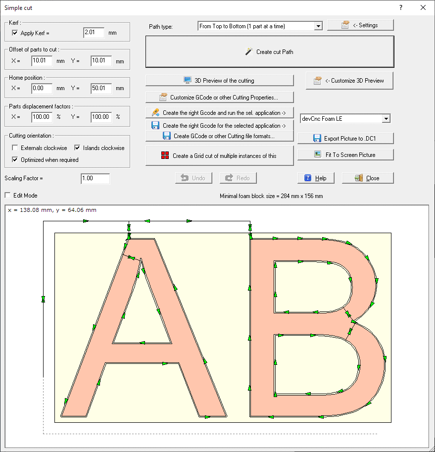
The following dialog will appear:

Using this feature the text or shapes (we'll call them Parts
now) will be cut without moving their placement You can just modify the
distance, see below).
This is useful if you for example want to cut a negative text (you will use the
surrounding foam material) or if you already drawn the Parts at the right place
and angle.
The basic idea in this dialog is to create the right
Cutting path and to send it to your Foam Cutting CNC machine
In the left part of the dialog you can see some parameters
required to create the
Cutting path :
-
Kerf frame - you can select here if you
want to apply the
Kerf
-
Offset of parts to cut frame -
you specify how far from the 0, 0 origin the bottom/left corner of the
rectangle surroinding the Parts will be placed
-
Home position frame - you specify here
the X and Y coordinates of the Home of the
Cutting path. The Home is the point where the
Cutting path start and finish.
-
Parts displacement factors
frame - you modify here the horizontal (X) and vertical (Y) distance among
parts, specifying a factor. Using 100% the original palcement will be applied.
-
Scaling factor - you can rescale the
Parts, the default value is 1.0
-
Cutting orientation -
you can specify the cutting orientation for External and Internal
(Island/Holes) contours. Selecting 'Optimized when required', the external path
can be changed when islands are included, to cut the shortest external contour
before. This can avoid the internal cut to move down.
-
Edit mode - if you enable this check box
you can move the entry/exit points of the
Cutting path, after you created it. See below for details
In the right part you can see some buttons, to create,
customize and export the cutting Path:
-
Path type: you can select here the type
of the pattern you are gong to create. Possible choiches are:
-
Shorter Path (inline cutting). This type creates the
shortest path, but the Parts are not cut one at a time, and also the Top to
Bottom order cannot be guaranteed.
-
From Top to Bottom (1 part at a time) - This type cut 1
part at a time, in a Top to Bottom order.
-
Smart Grid. from Top to Bottom - This type cut 1 part at a
time, in a Top to Bottom order, similat to the prevous mode. But here the
application try to understand if the parts are placed in a grid, and cut them
in grid mode in this case.
-
-
Create cut Path - this is the main
button, as creating the
Cutting path is the first operation to do. Click the button and
the
Cutting path will created automatically. You can then modify the
entry/exit points by enabling the
Edit mode checkbox and
dragging the blue control points
-
-
Customize GCode or other Cutting Properties...
- clicking this button you can see a popup menu wher you can:
-
We are making partnership with Companies supplying
good controllers and the related Gcode interpreter for Foam cutting.
You can select one the approved controller/applications then:
-
Press the 'Run the selected
app. ->' button to create a special GCode file customized
for the selected controller/application and run the application with the right
file already loaded
-
Press the 'Create the right
Gcode for ->' button to create a special GCode file
customized for the selected controller/application
-
Create GCode or other Cutting file formats...- clicking
this button you can see a popup menu wher you can:
-
Export Path to 2 Axis Gcode - if you are
driving your foam cutting machine as a simple 2 axis, this is the button to
create the GCode. You can customize the GCode using the
Customize 2 Axis Gcode button
-
Export Path to 4 Axis Gcode - if you are
driving your foam cutting machine as a 4 axis, this is the button to create the
GCode. You can customize the GCode using the
Customize 4 Axis Gcode button
-
Export Path to DXF - DXF files are a
standard in Cad applications. You can customize the DXF using the
Customize DXF button
-
Export Path to DAT - DAT files are used
to describe a single polyline, some CNC driving software likes to import them
-
Export Path to Hpgl/Plt - Hpgl/Plt files
are used to describe the plotting of a drawing, some CNC driving softare likes
to import them. Only simple command like SP, PU, PD are used here.
-
Export Path to GMFC script .CUT file - if
you use GMFC to drive your CNC, you can create a .CUT file and import it in
GMFC as a Script file. When you click this button you will be prompted for some
parameters in the
GMFC
.cut file creation dialog
-
Create a Grid cut of multiple instances of this
- clicking this button the
Grid cut dialog will appear. You can create here an array of
cells, where every cell includes the cut you have created here. In this
way you can create a complex cut of multiple items in a very simple way.
-
Undo - Redo - you can undo/redo the
modification to the
Cutting path
-
Fit to screen picture - you can maximize
the content of the picture
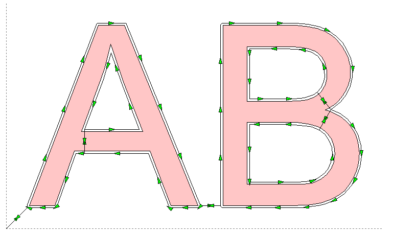
Clicking the Create cut Path button
the Path will be created and displayed to the picture, see the example below:

You can see now a black polyline (the
Cutting path) with some arrows showing the cut direction.
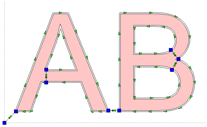
You can move the entry/exit points and the Home position enabling the Edit
mode checkbox.
See the picture showing what happens enabling it:

Now you can see some Blue control points. You can drag and
drop them to move the entry/exit points and the Home position.
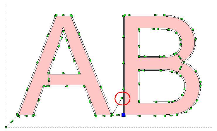
When you drag a Blue control point on the Cutting path also some little green
squares are added: they shows the Vertices of the Cutting Path, so you can move
the point to an existing vertex. The green square also works as snap points, so
if you stay near them with the mouse, they will capture the mouse pointer. If
you want cancel the current moving press the 'Esc' button.
If you drop the control point to an invalid part of the cutting path you are
alerted by a message and the operation is aborted.
You can use Undo/Redo buttons to Undo/Redo this operations.
See below what happen when you drag a control point: you can see in the red
circle (added only here to better explain) the point you are moving and a line
connecting the other point of the original connecting line.

When you are in Edit mode, if there are identical parts in
the drawing, you can see a combo box where you can select the way the editing
affect identical parts:
-
Apply only to selected part: in this case
the editing will affect only the single part
-
Apply to identical parts with same Blue Point:
in this case the editing will affect also the identical Parts having the same
Entry/Exit point
-
Apply to identical parts: in this case
the editing will affect also the identical Parts
Once the
Cutting path is right for you you can export it in the format you
prefer using the buttons included in the upper/right side of the dialog.
You can them import/open this file in the application you use to drive your
CNC, see also How can I send the work done in devFoam to my Foam
Cutting CNC machine?
More info about the picture in this dialog:
-
You can Zoom In/Out using the mouse wheel
-
If you are not in editing mode, clicking a point
inside the dialog you go in 'Distance' mode. When you move the mouse the
distance and angle from the clicked point are displayed in the upper/left side.
Clicking again a point the Distance mode will exit
-
Clicking the right mouse button a contextual menu will be
displayed, showing some more features.
I suggest also to take a look at
this page, to better understand some important concepts of devFoam:
DevFoam FAQ and important concepts


